№ 1606-T1436001
Introduction
Thank you very much for purchasing the side skirts. This document describes procedures and precautions for installing and using this product. Please be sure to read it before installation and carry out correct installation and handling. Be sure to hand these handling precautions (for the customer using the product) to the customer.
The following symbols are displayed for important points, which must be observed.
| Note | |
|---|---|
| ⚠️ Warning | Safety precautions that must be observed (Improper handling may result in death or serious injury) |
| ☝️ Advice | Describes information that is useful for performing the work efficiently. |
☝️ Advice
This product cannot be installed on unregistered vehicles. Installation must be performed after vehicle registration.Part Number・Compatible Vehicle Models
| Part number | Paint color | Notes |
|---|---|---|
| MS344-18004-A1 | Crystal White Pearl (K1X) | MY2017-MY2020/Kouki |
| MS344-18004-C0 | Crystal Black Silica (D4S) MY2017-MY2020/Kouki | |
| MS344-18004-D1 | Pure Red (M7Y) | MY2017-MY2020/Kouki |
| MS344-18004-E0 | Orange Metallic (H8R) | MY2017-MY2020/Kouki |
| MS344-18005-NP | Unpainted (Primer-Treated) | MY2017-MY2020/Kouki |
- For the latest compatibility information, please visit the TRD catalog site. trdparts.jp
Parts Manifest
| No. | Product name | Qty | Notes |
|---|---|---|---|
| ① | Side skirt RH | 1 | |
| ② | Side skirt LH | 1 | |
| ③ | J‑nut | 4 | |
| ④ | Tapping screw | 4 | 6×20 |
| ⑤ | Clip | 4 | (for φ7 dia.) |
| ⑥ | Clip | 2 | (for φ6 dia.) |
| ⑦ | Clip | 10 | (for φ18 dia.) |
| ⑧ | Template | 1 | |
| ⑨ | Installation manual (this document) | 1 |
The following items are included only with MS344-18005-NP (Unpainted Parts Set)
| No. | Product name | Qty | Notes |
|---|---|---|---|
| ⑩ | Moulding (only included with unpainted set MS344‑18005‑NP | 2 colors | each 2 pieces, approx. Length=2200mm) |
| ⑪ | PAC primer | 1 | K‑500 |
Confirmation: Upon arrival of this product, immediately check that the main unit is undamaged and that all accessories are included.
Parts List

(Page 2)
Installation Precautions (For Installers)
⚠️ Warning
- Do not modify or process this product, and do not install it on vehicles other than those listed as compatible. Doing so may cause serious accidents or failures.
- Follow the repair manual for the applicable vehicle (issued by Toyota Motor Corporation) and observe the precautions in this document when installing or replacing this product.
- Tighten all fasteners to the specified torque values. Insufficient tightening may cause the product to come off, leading to serious accidents or failures.
- Before installation, check that all main and component parts are present and that there is no damage or defect. Claims for damage or defects discovered after installation may not be accepted.
- To prevent scratches, handle the product on a protective sheet, and protect the vehicle body around the installation area with suitable protective material. Take sufficient care to avoid scratching or damaging the product or vehicle during installation.
Degreasing Work
Also refer to the separate “Degreasing Procedure” sheet.
- When performing degreasing, use a clean cloth and use white gasoline, isopropyl alcohol (IPA), or “Silicone Off” handled by TACTI Co., Ltd., to degrease thoroughly. Do not use silicone-off products other than the specified one.
- Do not use body coating base agents, parts cleaners, brake cleaner, or other solvents for degreasing. Inadequate degreasing will cause lifting and peeling.
Double‑sided Tape
- If degreasing is insufficient, the double‑sided tape will peel off even if it is applied.
- Once the double‑sided tape is applied and then peeled off, its adhesive strength will decrease and it cannot be reused.
- The adhesive performance of the double‑sided tape supplied with this product is significantly reduced at ambient temperatures of 20 °C or lower. If the temperature is too low, the tape may peel.
- Press the double‑sided tape firmly with a pressure of at least 49 N (5 kgf, enough to make the vehicle shake lightly). Insufficient pressure will cause peeling.
- For 24 hours after installing this product, do not allow car washing, water (including wiping with water), or rain to contact the product. Failure to observe this may cause lifting or peeling.
Painting Work for Unpainted Product
- Before painting this product, undercoat treatment is required. Always start with surfacer (primer) painting.
- When painting this product, mask all double‑sided tape areas completely.
- When drying, fix the product in a way that prevents deformation. High drying temperatures may cause deformation or cracking; therefore, dry at 70 °C or lower.
After Installation
- After installation, check that this product does not interfere with the vehicle body.
- If you disconnected the negative terminal of the battery during work, be sure to perform system setting and confirmation after completing the work.
(Page 3)
Table of Contents
- Cover, compatibility list, components list, component diagram … 1
- Installation / handling precautions (for installers) … 2
- Table of contents, required tools / protective equipment / consumables, preparation … 3
- Installation procedures … 4–8
- Post‑installation checks / inspection … 8
Required Tools, Protective Equipment, Consumables
- Cutting tools (scissors, cutter, etc.)
- File
- Safety glasses
- Work gloves
- Protective sheet
- Protective tape
- Masking tape
- White gasoline or isopropyl alcohol (IPA)
- Clean cloth (lint‑free)
Installation Layout Diagram
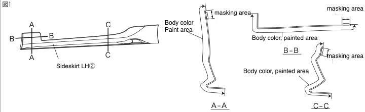
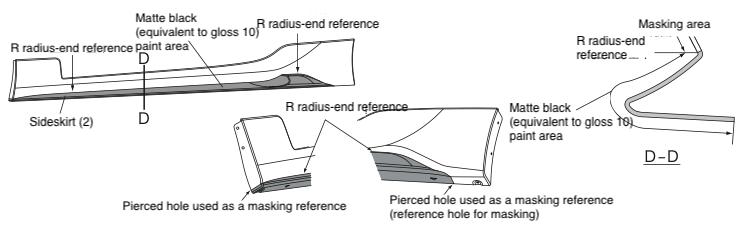
Painting the Side Skirts
Note: These instructions mainly illustrate the LH side. Perform the same procedures for the RH side.
⚠️ Warning
- When degreasing, use IPA or white gasoline. Do not use silicone off or thinner, as there is a risk of dissolving the primer.
- If the drying temperature exceeds 70 °C, deformation or cracking of the product may occur. Pay close attention to drying temperature. When force drying, fix the product so that it does not deform.
- Do not paint the moulding attachment surface or double‑sided tape surfaces. Adhesive strength will be reduced. Mask these areas using masking tape, etc.
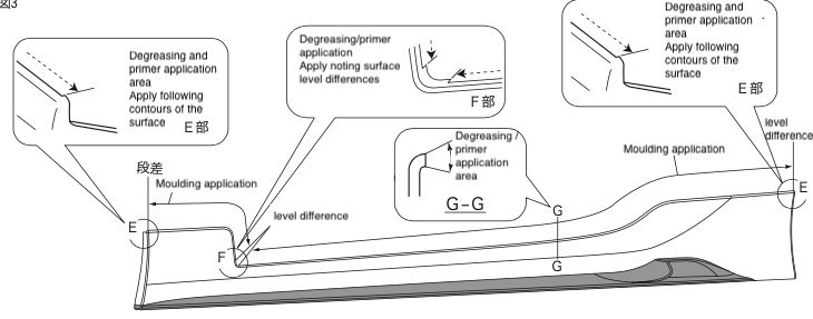
(Page 4)
Degreasing and Primer Application for Moulding
⚠️ Warning
- When performing degreasing, do not use solvents other than those specified. Remaining oil/grease can cause tape to peel.
- If the primer spreads beyond the specified area, it may cause staining. Apply carefully.
☝️ Advice
- When performing degreasing, do not use solvents other than those specified. Remaining oil/grease can cause tape to peel.
- If the primer spreads beyond the specified area, it may cause staining. Apply carefully.
- After degreasing and applying primer, allow it to dry for at least 10 minutes.
(Page 5)
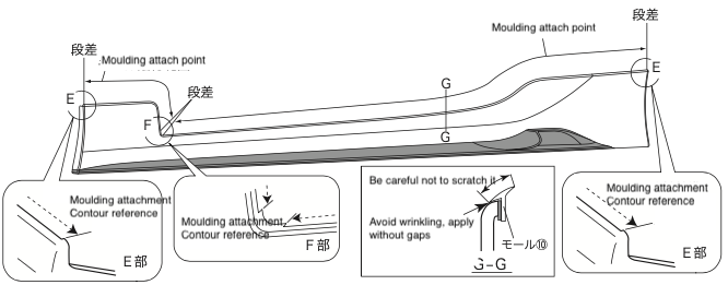
☝️ Advice: The molding is cut longer than needed. Trim it to the correct length using scissors or similar tools.
☝️ Advice: To maximize the adhesive strength of the double-sided tape, warm both the tape surface and the spoiler's mounting area to approximately 40°C (104°F) using a hair dryer or similar device before application.
☝️ Advice: Molding ⑩ is packaged with two colors. Select the molding color matching your paint finish and apply it accordingly.
Preparation for Installation on Vehicle
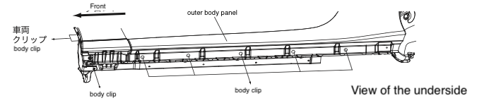
- Remove the vehicle clips (6 positions per side). The removed clips will not be reused.

- Remove dirt from the indicated areas on the underside. Wipe in one direction with IPA or white gasoline to degrease.
- If there is sealant on the attachment surface, remove it completely and touch up the exposed panel surface with touch‑up paint.
(Page 6)
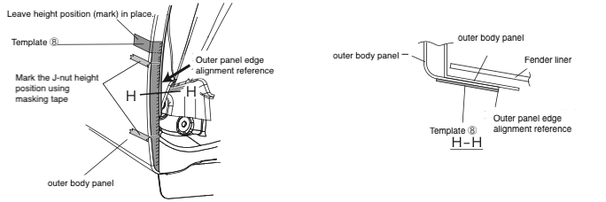
- Cut out template ⑧ and align it to the shape of the rear wheel house area, then affix it with masking tape.
- Using template ⑧, mark the height position for J‑nuts ③ on the masking tape.
- Remove template ⑧, leaving only the height mark for the J‑nuts on the masking tape.
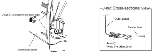
- As shown in Fig. 10, insert J‑nuts ③ (2 positions per side) at the marked positions on the rear wheel house area, aligning the lower edge of the J‑nut with the marked line.
- Remove the masking tape used for the J‑nut③ height mark.
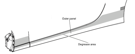
- As shown in Fig. 11, remove dirt from the side skirt ② attachment area on the vehicle outer panel and wipe in one direction with IPA or white gasoline to degrease.
(Page 7)
Installation Instructions
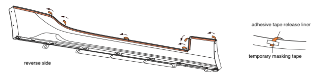
⚠️ Warning: If you peel off all release liners of the double‑sided tape except at the specified sections, correct positioning of the product will not be possible.
- As shown in Fig. 12, peel back approximately 30mm of the release liner of the double‑sided tape on side skirt ② (6 positions per side) from the front toward the rear, and temporarily secure the peeled liner on the outer surface with masking tape, etc.
☝️ Advice: Perform installation of this product with at least two people. ⚠️ Warning: When installing side skirt ②, take care not to scratch the vehicle outer panel.
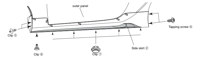
- Figure 13: Align side skirt ② with the vehicle outer panel and attach clips ⑤ (2 positions per side), clip ⑥ (1 position per side), and clips ⑦ (5 positions per side). Temporarily tighten tapping screws ④ (2 positions per side).
(Page 8)
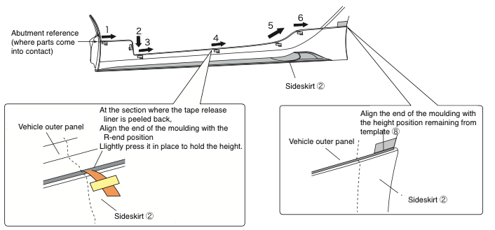
- (See Figure 14) Adjust the installation height of side skirt ②, check that there is no gap with the vehicle outer panel, then peel the release liners of the double‑sided tape (6 locations) in numerical order while pressing to bond them firmly. Required pressure: at least 49N/5kgf.
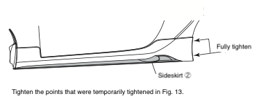
- (See Figure 15) Fully tighten tapping screws ④ (2 positions per side) that were temporarily tightened in Fig. 13.
- Peel off the remaining product height position on template ⑧. (One spot on each side)
☝️ Advice
- Excessive tightening torque may damage tapping screws and J‑nuts. Tighten only to the specified torque.
- To maximize the adhesive strength of the double‑sided tape, warm both the tape area and the vehicle attachment area to about 40 °C with a dryer before attaching.
- If the release liners of the double‑sided tape are not removed in the instructed order, gaps may occur.
- Do not wash the vehicle within 24 hours after the double‑sided tape has been bonded.
- The adhesive strength of the double‑sided tape becomes stable within about 3–5 hours. After installing the product, ensure an open (static) time of at least about 3 hours during which strong vibration or wind pressure (including vehicle movement) does not act on the product.
Post‑installation Checks and Precautions
- Check that the side skirts are securely attached to the vehicle by the tapping screws and clips.
- Check that the side skirts and vehicle parts have no scratches.
- Check around the entire product to ensure there is no lifting or peeling.